tl;dr
I led the design, manufacturing, and autonomous programming of a sumo-style robot for the annual Caltech ME 72 competition. Below is a summary presentation of all the content outlined in detail throughout this post.
Overview
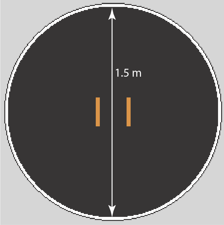
The ME 72 course sequence provides students with rigorous team-based engineering design and fabrication experience. The course is based around a design competition theme, with this year's being sumo robots! Teams are formed at the start of the course and challenged to design and fabricate robotic devices that must conform to the documented rules and physical constraints of the design competition. The class provides students with integrated engineering design experience that emphasizes computer-aided (CAD) mechanical design, physical machining of individual piece parts, and the implementation and digital (remote) control of mechatronic sensors and actuators. Students also gain considerable experience with commercially available open-source electronics platforms such as Arduino microcontrollers or Raspberry Pi computers. Here I'll detail our team's progress throughout the 20-week competition as well as our final performance. The general rules and playing field of the competition are as follows:
Robot types: Each team is responsible for three categories: (1) wheeled R/C, (2) wheeled autonomous, and (3) walking R/C. We are allowed to use the same wheeled robot for both R/C and autonomous categories, provided that none of the R/C functionality is present in the autonomous portion, and vice versa.
Match format: The goal of each round is to knock the opposing robot off of the "dohyo" pictured below. A match between two teams consists of three rounds, one with each robot type. The team that wins the majority of the three rounds wins the match.
Robot restrictions: Mass limit of 3 kg, size restriction of 20 cm (length) x 20 cm (width) x unlimited height. Robots may not have any actively actuated mechanisms besides wheels/legs or any forms of electrical interference. There is also a strict $1200 limit for all parts.
Competition day: Teams first play against each other team once in a round robin style format. The top four teams then move on to single elimination rounds until an ultimate winner is declared.

Research & Design
I elected to work on the two categories with a wheeled robot, as I have plenty of relevant experience with wheeled robots in high school. hence, all of the work shown below was contributed to directly by myself. That being said, the first step was some important priorities for our robot's design. The first priority was high consistency over high ceiling. Losing even 1 of the 3 games is a huge disadvantage, so we want to reduce the chances of losing over avoidable things like easily-breakable components that give only mediocre return value. The second priority was repairability over efficiency. It's very enticing to try and pack the robot into a super dense chassis with tight tolerances, but the reality is that most matches will be decided by a single high-speed impact, and matches go by in a matter of minutes. While designing to minimize failure is always a priority, it's important that we are able to replace components that do break quickly, lest we show up to a match without a fully-functioning robot. The last priority was placing an emphasis on existing knowledge. Because this competition is so similar to the sumo robot leagues found all around the world, there are plenty of available resouces online. One of the most useful was the JSumo website, which not only contains valuable knowledge and experience from real competitors but also acts as a store for some of the more novelty items we will need for our robot (e.g. hard wheels).
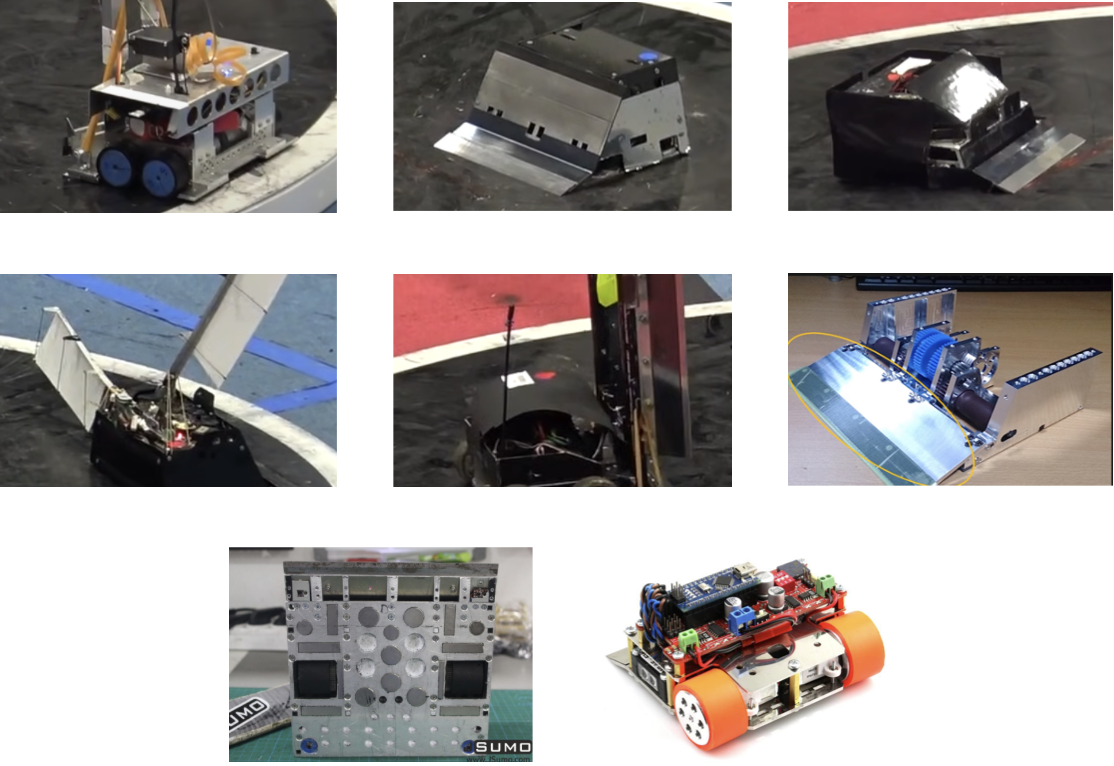
With these priorities in mind, we began by doing some thorough research and classification of the strategies that existing teams use. We found that robots can be split into roughly three types: torque, balance, and speed. Torque-heavy robots typically move under 0.5 m/s and achieve between 70-100 kg of downforce from magnetic attraction to the dohyo floor. Balanced robots typically move between 2-5 m/s and achieve 40-70 kg of downforce. Speed-heavy robots typically move between 5-7 m/s and achieve 15-40 kg of downforce. In terms of interactive mechanisms, most robots chose to have a simple static wedge, but some exhibited passively-deployed arms (used to get a larger wedge) and distractive surfaces (used to trick opponents into attacking the wrong area). Virtually all robots used two-wheel drive, had magnets on their baseplate, and were constructed out of aluminum. For ease of visualization, I've provided some pictures of robots with these trends below.
After considering these popular trends in the context of our priorities, we arrived at the high-level design listed below. Next, we go into the low-level of each mechanism including specific parts, first principles, and manufacturing techniques.
Drivetrain: "Balance" class, ~5 m/s and ~50 kg downforce. Two-wheel drive placed slightly behind the robot's center of downforce with caster bearings in front.
Contact mechanism: Static, full-width wedge. Goal is to make it as long as possible and hinge it to prevent flips. This is something we have not seen any existing robots do, but it wouldn't be too hard to implement and doesn't significantly contradict our priorities, so we decided to go for it.
Other considerations: Be as low to the ground as possible, have a dark exterior to confuse opponent's IR sensors, leave lots of magnet holes on the base for adjustable downforce should we want to stray from ~50 kg.
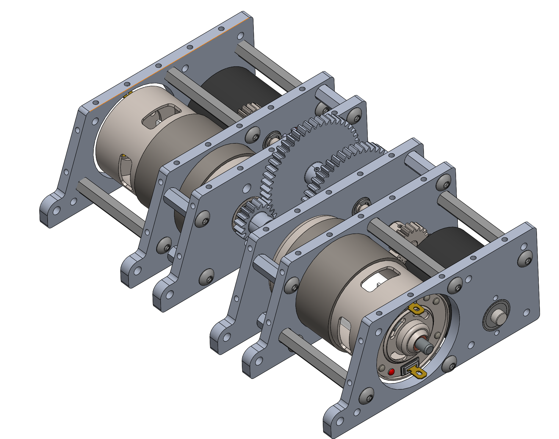
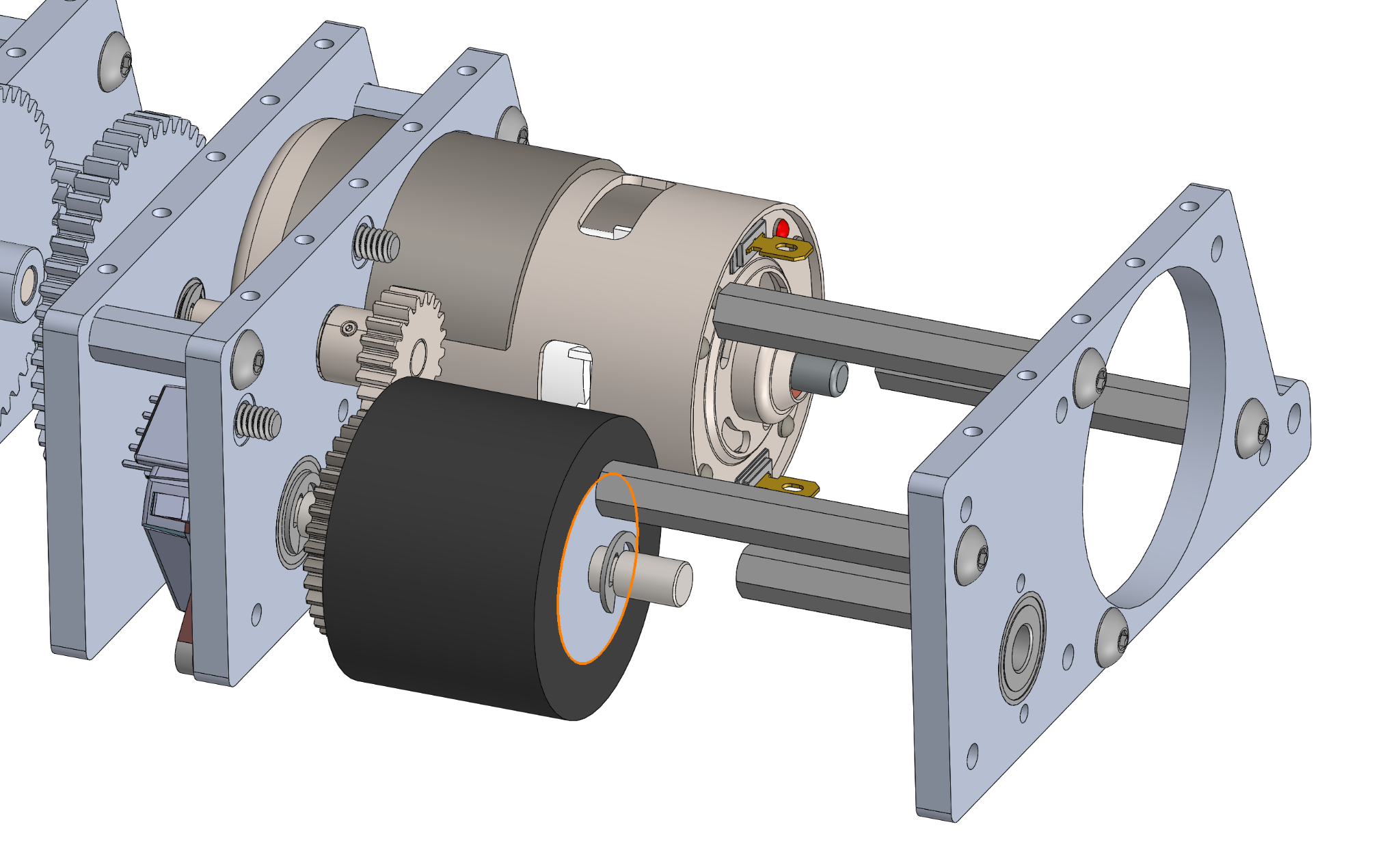
Gearbox
Given the strict budget, we opt for the cheap and easily-sourceable RS-775 24 V motors. From the gears in stock at SDP/SI we were able to form a 4.8:1 reduction for a theoretical maximum speed of 5.5 m/s. To make sure this is feasible given the motor's stall torque of 0.85 Nm we invoke . For our hard rubber wheels cm and . Keeping in mind the 4.8:1 gearing and 4 total wheels, we find the torque induced by static friction on each motor to be:
This is well within the motor's stall torque. Other notable calculations are an ideal acceleration of 110.9 m/s^2, time to top speed of 0.05 s, and time to cross the entire dohyo of 0.253 s. With this validation, we can now CAD the gearbox to include the following components and specifications:
Wheels: JSUMO Rubber 64 shore. 40 mm (D) x 30 mm (W).
Motors: RS-775 24 V. 12600 no-load RPM.
Gearing: Two-stage reduction. First stage 48T/16T, second stage 32T/20T. Gears positioned with E-clip retaining rings, all shafts supported by two press fit bearings.
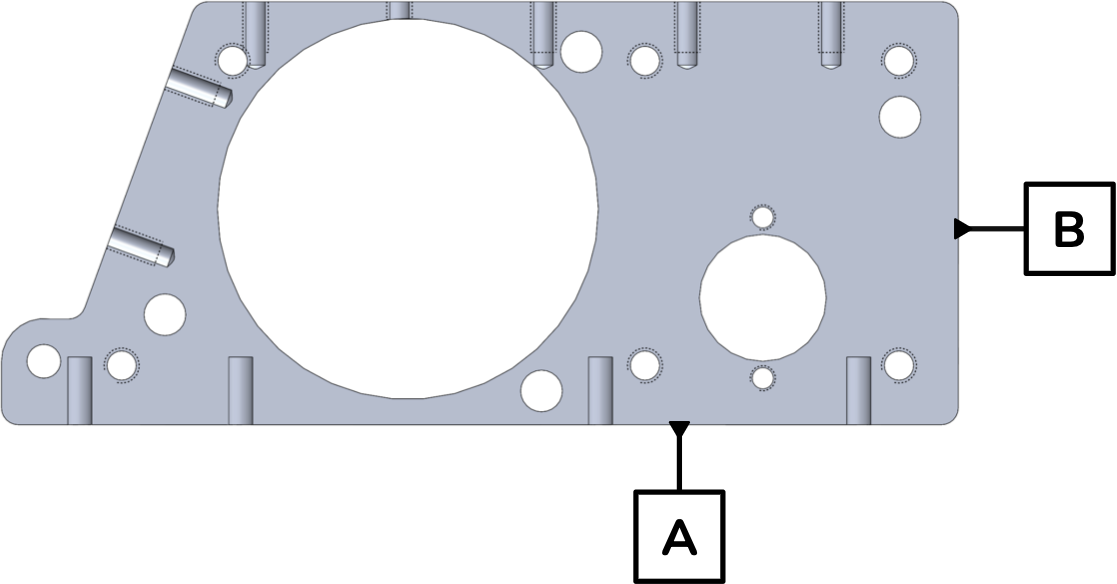
Housing: 5 mm aluminum plate, standoff connections for rigidity, M3 screws.
Sensors: AMT 103 quadrature encoders.
As the gearbox is made of six separate aluminum plates, manufacturing would take some time. Each plate was made following this rough process:
Waterjet shape and motor hole.
Mill it square and flatten surfaces. Establish datums A, B, and C to ensure perpendicularity.
Bring top, left, and bottom surfaces in relative to datums A and B.
Mill holes that need to be accurate relative to datums A and B.
Tap holes relative to datum C in the mill. Note that datum C is important as we need to establish distances between each plate inside the gearbox.
A short timelapse of gearbox construction can be found below:
Baseplate
The baseplate is very simple in comparison to the gearbox. All it needs is some M2 screwholes that feed into each gearbox plate and some holes for wheels, line sensors, magnets, etc. In terms of magnetization, we found some cheap but powerful neodynium magnets on Amazon, where 8 magnets is about the 50 kg we are targeting. Our design specifically places the base plate as close to the ground as we can (~1 mm) to provide the most amount of downforce per magnet. In terms of manufacturing, all we need to do here is waterjet the general shape and holes and then mill out the screw holes as those need to be countersunk. Not much else to it here.
Wedge and Hinges
As mentioned earlier, our "innovation" for this competition was to have a hinged wedge versus a static one. It is sprung down to avoid easily bouncing up, but it's not actively actuated so within the rules. The purpose of the hinged wedge was to improve consistency. If an opposing robot's wedge gets under ours and we have no hinge, they will lift our entire robot off the ground and render our magnets useless, allowing them to push us off the dohyo with ease. By hinging our wedge, we now have a safeguard—should the opposing robot get under our wedge, now they just lift our wedge off the ground and not our entire robot. This leaves our downforce intact and increases our chances of survival significantly.
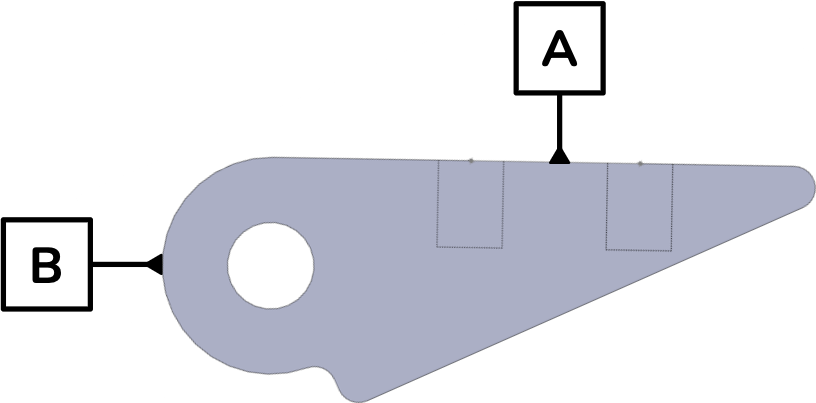
Wedge: Made of 3mm thick aluminum and oriented 25 degrees off the ground. The portion in contact with the ground has a portion shaved off at the same angle so that it stays flat. Attached via four strong hinges rigidly attached with three M3 screws each.
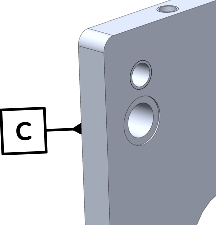
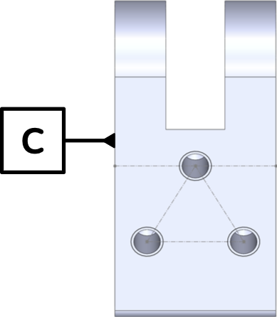
Hinges: Custom machined, rotate around holes made in the gearbox plates. Each uses a 4mm aluminum pin with loose fit. This makes for easy rotation while guaranteeing that the pins fail before the hinges under compression (e.g. an impact with another robot). This is very important because it's very easy to replace the pins, but very annoying to remake an entire hinge.
The wedge is manufactured very similarly to the gearbox plates by establishing three datums, flattening, and making holes relative to one. The hinge is a little more complicated and requires some automated machining on the CNC:
Begin with oversized prism stock.
Flatten and face all sides on the mill. Establish datums A, B, and C to ensure perpendicularity.
CNC the shape of the side view using toolpaths generated from our CAD.
Mill the side through hole using a drill chuck, then the centered slot with an end mill, and lastly the three top holes with a drill chuck again.
A short timelapse of hinge and wedge attachment to the gearbox and baseplate can be found below:
Electronics
Sensors: 4x IR line sensor, cheap and accurate up to 1cm off the ground. 3x ultrasonic sensors, slightly slower than IR but very useful because they are sound-based and thus won't be affected by opposing teams using dark surfaces on their exterior. 2x AMT 103 quadrature encoders as described before. 1x 3-axis gyroscope for turn estimation.
Motor controllers: Single Roboclaw unit for easily-tunable PID and integration with encoders.
Batteries: 2x TATTU 12 V 1300 mAh LiPo batteries, providing a total of 31.2 Wh. With motors operating at full 7.1 A we get about 5.5 minutes of operation, which is more than enough for each 3-minute match. Realistically, most of these matches won't last more than 30 seconds anyway but better safe than sorry.
Control board: Originally wanted to get a Teensy board for more computing power, but due to cost constraints we stuck with an Arduino Mega.
Autonomous Strategies
We found many different autonomous strategies in our research, some of which performed better than others. Almost all of them consisted of some basic exploration method around the dohyo until the opposing robot is identified, followed by a concentrated attack. Some of these strategies are outlined below:
Rotation search: Spin in circle until enemy detected or edge is found. Basic but actually very effective.
Tornado search: Rotation search, moving slightly after every full turn.
"Woodpecker" search: Moving with slight increments straight toward center. Tended to lose a lot.
Edge search: Specifically searching toward the edges of the ring.
Bait and switch: Let opponent charge, quickly move away so they fall off. Alternatively, gives you the option of charging the opponent from their side which is much more vulnerable than their front.
Slow spline following: Salculate path (roughly sinusoidal) that minimizes distance robot travels while covering entire surface area with sensors (requires knowing precise sensor ranges).
Wobbler search: Pick a direction and travel 1x distance, then 2x in opposite direction, then 3x, etc.
Random drive search: Randomly pick a direction and distance, correcting hard if an edge is found and attacking if an enemy is found.
Circular attack: Measure distance from opponent at the start, circle around to hit directly from the side. Adjust target spot based on perceived trajectory. Requires very accurate odometry.
Given how many potential strategies there were to choose from and how complex it would be to map out which ones are more effective against others, we decided to use a combination of all of them, which we called our dynamic strategy selection. The premise is pretty simple: start with some initial strategy X, and if X has not found the opponent within some number of iterations, switch to another strategy Y. Here's some Arduino pseudocode that accomplishes exactly this:
Of course, any autonomous strategy is going to be reliant on good odometry and pathfinding. The pathfinding is specific to the strategy we are currently implementing, but the odometry roughly follows the code shown below and can be used as a basis for your own robot:
Competition Day Results
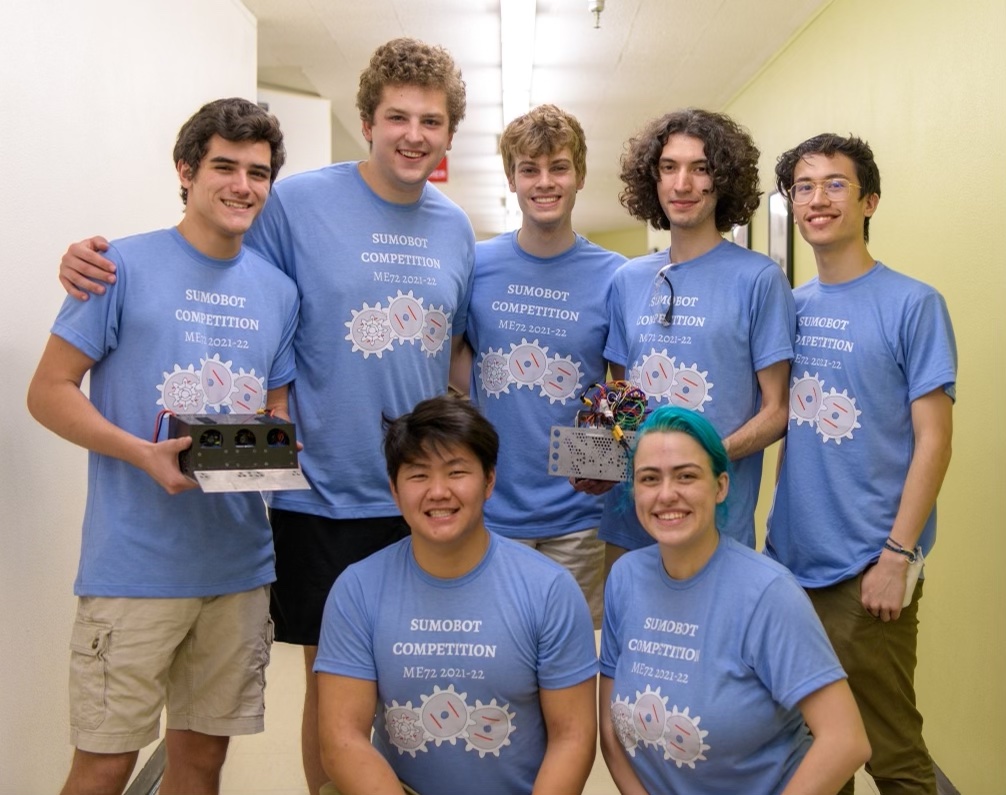
After a very long week of all nighters spent debugging and making minor mechanical tweaks to each robot, we woke up bright and early on the morning of March 8th, 2022 for the final competition. In the round robin portion, the autonomous wheeled robot won all but one match. The R/C wheeled robot also won all but one match, and the R/C walking robot won every match. We handidly made it to the single elimination portion, where the autonomous and wheeled robots continued performing well. Sadly, the walking robot had a major mechanical failure that would take hours to fix, rendering it unable to compete. With this major blow, we lost and came in second overall. Here's a nice picture of the whole team with our completed robots after it was all said and done.
Reflection
In hindsight, it's very easy to see what the major challenges of the competition ended up being. For one, the $1200 budget was not enough to get the class of components we needed to mimic the real sumo robots found around the world, most of which cost well above double our budget, and we had to split our money among multiple robots. There were also some unfortunate interpretations of the official game rules, which is understandable (it's just a class) but really unfortuante as it caused some disturbances to our autonomous programming. Perhaps the single biggest challenge was simply time—this was a 20-week class, where many of the weeks we were unable to access the machine shop due to COVID restrictions. Additionally, our preliminary and critical design reviews were scheduled very early on in the class, which did not leave us very much time to do proper structural analysis and FEA on the robot's individual components. Most of our time was spent on assembly and testing and not enough on practicing.
If I could do it over again, and if any teams are looking into making a robot for the same competition, I would give the following pieces of advice. For one, use more magnets than we did. 50 kg of downforce was nice, but it was very difficult to move the other teams' robots that used more, and in one case doing so even cost us a motor! Speaking of which, I would definitely recommend looking at brushless motors versus the brushed RS-775s that we used. They are more expensive, but are much less likely to break and will give you much more pushing power, especially if you are using more magnets. I'd also recommend not using a Roboclaw as the dedicated motor controller—it's very convenient for setting up the electronics quickly, but due to it being a separate component, it caused our code's loop time to be pretty high because of read delays. In terms of general priorities, I wish we'd spent less time programming different autonomous routines because our robot was already leagues ahead of the other teams in this category. In fact, I'm pretty sure we were the only team to have sensing and pathfinding implemented for the competition; most other teams just randomly moved across the dohyo waiting to hit something.
Overall, I'm incredibly happy with how we performed. Even with all of the major challenges described above, we were able to throw together two very solid robots that, when no untimely mechanical failures occured, were crowd favorites and almost always beat out the competition. This was one of, if not the, best classes I have ever taken and highly recommend to anyone looking into the Mechanical Engineering curriculum here at Caltech.